Truss Education
Lesson 1: Ordering Trusses
Lesson 2: Handling, Installing, Bracing
Lesson 3: Installation
Lesson 4: Truss Design Considerations
Lesson 5: Definitions
Lesson 1: Ordering Trusses
- Bearings
- Spacing
- Design (Specified) Loads
- Typical Roof Truss Design
Specify all exterior and interior points of bearing, showing location by dimension and size. Reaction forces at point of bearing may affect the required size of bearing surface to prevent crushing.
Give center-to-center spacing of trusses. If trusses are spaced greater than 24 inches center-to-center, it is necessary to indicate the purlin spacing and method of attachment to the trusses.
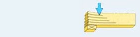
Truss design (specified) loads include both live and dead loads which may be uniformly distributed or may be concentrated at various locations.
LIVE LOADS: Live loads are non-permanent loads. Environmental loads produced by snow, wind, rain, or seismic forces are live loads. The weight of temporary construction materials and occupant floor loads are live loads. Live loads are usually uniform in their application and are set by building codes or building designer. Live loads will vary by location and use and should be furnished in pounds-per-square-foot, or other clearly defined format. DEAD LOADS: Dead loads are the weight of the materials in the structure and any items permanently placed on the structure. SPECIAL LOADS: Special loads can be live or dead. Examples of special loads might include mechanical units, poultry cages, cranes, sprinkler systems, movable partition walls, etc. The weight, location and method of attachment must be provided to the truss designer. Multiple load cases may be required in truss design.
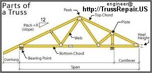
Click on the image to view a diagram of a designed truss with explanations of its parts.
Lesson 2: Handling, Installing, Bracing
- Responsibility
According to the publication Standard Responsibilities in the Design Process Involving Metal Plate Connected Wood Trusses (WTCA 1-1995), published jointly by the Wood Truss Council of America (WTCA) and the Truss Plate Institute (TPI), responsibility for wood trusses is divided among the owner, building designer, the contractor or builder (installer) and the truss manufacturer.
The truss installer is responsible for safe handling, installation and both temporary and permanent bracing of the trusses after they reach the job site.
A good guide for these areas of responsibility is Handling, Installing an Bracing Metal Plate Connected Wood Trusses - HIB-01 published by the Truss Plate Institute (TPI). The publication is also available in a six page fold-out summary form for use as a job site reference. It is recommended that all persons associated with the installation process read and adhere to the recommendations of this publication to help prevent injury to themselves, other workers and property.
A good publication for guidance in the design of a temporary bracing system is the publication Temporary Bracing of Metal Plate Connected Wood Trusses, DSB-89, published by the Truss Plate Institute (TPI).
WARNING:
Do not cut or notch any truss member without permission of the truss designer.
Do not use or repair damaged trusses without professional consultation with the Architect, Engineer or Truss Designer.
Lesson 3: Installation
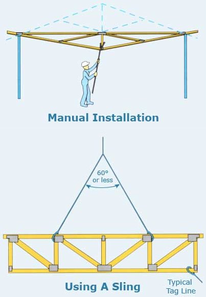
Trusses may be installed manually, by crane, or by forklift, depending on truss size, wall height and job conditions. Individual trusses should always be carried vertically to avoid lateral strain and damage to joints and members.
Trusses installed manually are slid into position over the sidewall and rotated into place using poles. The longer the span, the more workers needed to avoid excessive lateral strain on the trusses. Trusses should be supported at joints and the peak while being raised.
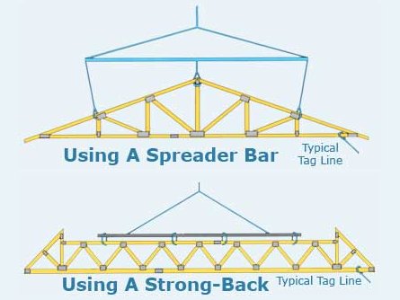
Large trusses should be installed by a crane or forklift employing chokers, slings, spreader bars and strong-backs to prevent lateral bending. Trusses may be lifted singly, in banded groups, or preassembled in groups.
Tag lines should always be used to control movement of trusses during lifting and placement.
Refer to Handling, Installing and Bracing Metal Plate Connected Wood Trusses (HIB-91) by the Truss Plate Institute, or Wood Truss Erection poster by the Wood Truss Council of America for proper methods of installation.
Installation procedures are the responsibility of the installer. Job conditions and procedures vary considerably. These are only guidelines and may not be proper under all conditions.
Lesson 4: Truss Design Considerations
- Types of Stresses to be Considered in the Design of Trusses
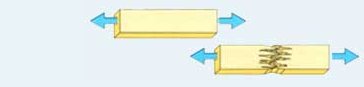
- Compressive Stress Parallel to Grain
- Tensile Stress
- Horizontal Shear
- Bending
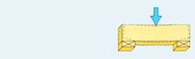
- Compressive Stress Perpendicular to Grain
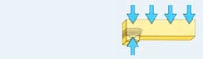
- Vertical Shear
- Loads in Wood Trusses
- Short Term Loading
- Duration of Load Adjustment
- Other Adjustments
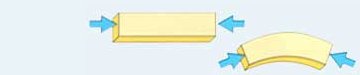
Truss top chords are generally in compression. When subjected to compressive stress, wood members can buckle. The longer and more slender the member is, the less compressive force it takes to buckle. In lumber, the compressive strength is measured by the Fc value.
When subjected to tensile stress, wood members can elongate. Truss bottom chords are normally in tension. In lumber, tension strength is measured by the Ft value.
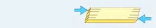
Horizontal shear occurs along the grain, causing fibers to slide over each other. In lumber, horizontal shear strength is measured by the Fv value.
Bending occurs between supports when lumber is subjected to loads. Bending strength is measured by the Fb value of the lumber.
An example of compression perpendicular to grain is the bottom chord sitting on the support. It is necessary that the bottom chord lumber area be sufficient to prevent side grain crushing. Lumber's resistance to crushing is rated by the Fc value.
An example of vertical shear occurs at the inside of the truss support. Wood is stronger in vertical shear than horizontal shear. Since a vertical shearing force produces both vertical and horizontal shear stresses, wood will fail in horizontal shear instead of vertical shear.
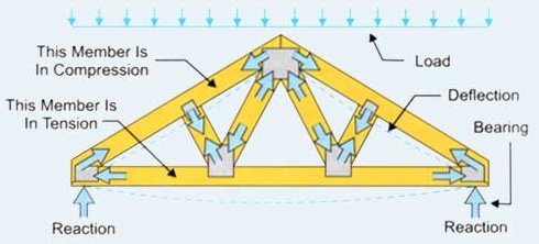
This truss illustrates the action of the various stresses occuring along the wood members. The applied loads induce stresses and movement in the truss members. A stable truss will resist these stresses. The wood members are designed to resist the stress according to the allowable design values published in the National Design Specification For Wood Construction (NDS). NDS is published by the National Forest Products Association. Forces at the member joints are resisted by metal connector plates that are held in place by "teeth" punched out of the base metal at right angles. The plates are rated for lateral resistance (tooth holding), shear, and tension and require review and approval by each of the model codes.
Wood has the ability of carrying a greater load for short durations than for long durations.
The table shows the more common types of loads, their expected accumulated duration and the factor of adjustment in the allowable lumber stresses and the lateral resistance value (tooth holding) of the connector plate. Note: the factors do not apply to shear and tension in the connector plate.
| Load Type | Duration of Load | Adjustment Factor |
|---|---|---|
| Dead Load | Permanent | .90 |
| Floor Live - Normal | 10 Years | 1.00 |
| Snow Load | 2 Months | 1.15 |
| Construction | 7 Days | 1.25 |
| Wind/Earthquake Load | 10 Minutes | 1.60 |
| Impact | Impact | 2.00 |
Other adjustments to design values may be necessary. The value of lumber in extreme fiber bending "Fb" may be increased when there are three or more trusses spaced not more than 24 inches on center and are joined by load-distributing elements.
In special single-member applications where deflection may be a critical factor, or where deformation must be limited, reduction of modulus of elasticity (E) value may be appropriate.
Lesson 5: Definitions
AXIAL FORCE - A push (compression) or pull (tension) acting along the length of a member. Usually measured in pounds (lbs).
AXIAL STRESS - The axial force acting along the length of a member, divided by the cross-sectional area of the member. Usually measured in pounds per square inch (psi).
BEARING - Structural support of a truss, usually wails, hangers or posts.
BENDING MOMENT - A measure of the bending effect on a member due to forces acting perpendicular to the length of the member. The bending moment at the given point along a member equals tine sum of all perpendicular forces, either to the left or right of the point, times their corresponding distances from the point. Usually measured in inchpounds.
BENDING STRESS - The force per square inch acting at a point along the length of a member, resulting from the bending moment applied at that point. Usually measured in pounds per square inch (psi).
BOTTOM CHORD - A horizontal or inclined (scissors truss) member that establishes the lower edge of a truss, usually carrying combined tension and bending stresses.
BUILT-UP BEAM - A single unit composed of two or more wood members having the same thickness but not necessarily the same depth, which provides a greater load carrying capacity as well as greater resistance to deflection.
CAMBER - An upward vertical displacement built into a truss, usually to offset deflection due to dead load.
CANTILEVER - The part of a structural member char extends beyond its support.
COMBINED STRESS - The combination of axial and bending stresses acting on a member simultaneously, such as occurs in the top chord (compression + bending) or bottom chord (tension + bending) of a truss.
CONCENTRATED LOAD - An additional load centered at a given point. An example is a crane or hoist hanging from the bottom chord at a panel point or mechanical equipment supported by the top chord.
DEAD LOAD - Permanent loads that are constantly on the truss, ie: the weight of the truss itself, purlins, sheathing, roofing, ceiling, etc.
DIAPHRAGM - A large, thin structural element that ants as a horizontal beam to resist lateral forces on a building.
DRAG STRUT - Typically a horizontal member, such as a truss or beam, that transfers shear from a diaphragm to a shearwall.
DURATION OF LOAD FACTOR - An adjustment in the allowable stress in a wood member, based on the duration of the load causing the stress. The shorter the time duration of the load, the higher the percentage increase in allowable stress.
LEVEL RETURN - Lumber filler placed horizontally from the end of an overhang to the outside wall to form soffit framing.
LIVE LOAD - Any load which is not of permanent nature, such as snow, wind, seismic, movable concentrated loads, furniture, etc. Live loads are enerally of short duration.
NOMINAL SPAN - Horizontal distance between outside edges of the outermost supports.
PANEL - The chord segment defined by two successive joints.
PANEL POINT - The centerline of the point of intersection in a joint where a web(s) meets a chord.
PURLIN - A horizontal member in a roof perpendicular to the truss top chord used to support the decking.
REACTION - Forces acting on a truss through its supports that are equal but opposite to the sum of tine dead and live loads.
SHEARWALL - A wall element that ants as a large vertical beam, cantilevered from the foundation to resist lateral forces on the building.
SPLICE POINT (Top or Bottom Chord Splice) - The point at which two chord members are joined together to form a single member.
TOP CHORD - An inclined or horizontal member that establishes the upper edge of a truss, usually carrying combined compression and bending stresses.
VIBRATION - The term associated with the serviceability of a floor. If the occupant feels the floor respond to walking or other input, it may be referred to as vibration or response to load.
WEBS - Members that join the cop and bottom chords to form the triangular patterns that give truss action, usually carrying tension or compression stresses (no bending).